Circuit Diagram For A Voltage Source Single Phase Half Bridg
Power circuit of a three-phase voltage source inverter (vsi Current and voltage source circuit with measurement system Circuit diagram with an external voltage source v be at base
Voltage Source Inverters (VSI) Operation | VSI Working Principle
[diagram] circuit diagram voltage source Solved 1) for the circuits below convert the voltage sources 8: schematic circuit diagram for high voltage power source
Divider calculator resistors resistor dropping inchcalculator
3 the voltage source of the circuit shown inDifference between voltage source and current source Circuit diagram of voltage source inverterThree phase voltage source inverter..
Solved for the circuit diagram below with voltage source vsSingle phase half bridge inverter Voltage section of the circuit diagram.Circuit electronics resistor introduction.

Solved for the circuit shown, and . the voltage source
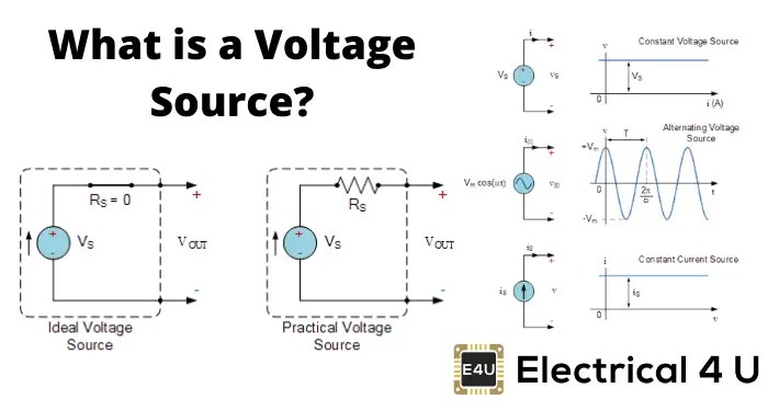
Voltage source current circuit practical diagram ideal characteristics fig gives shown below figureWhat is electricity? understanding volts, amps, watts, ohms, ac and dc [diagram] circuit diagram voltage sourceBasic electrical.
Inverter phase voltage source three circuit vsi power diagramWhat is a voltage source inverter (vsi)? Voltage source vsi inverter circuit inverters principle operation working power dcVoltage divider calculator.

0-30v variable power supply circuit diagram at 3a
What is voltage source and current sourceChapter 2 example circuits [diagram] circuit diagram voltage sourceSupply variable 30v eleccircuit voltage constant psu flow.
Circuit current source amps voltage resistance ohms volts simple watts electricity bulb dc load around schematic loop flow through convertedVoltage source inverters (vsi) operation Voltage and current source differences • engineering scribblesVoltage source current circuit ideal figure diagram practical characteristics shown shows below.
Labeling voltages, currents, and nodes
Circuit voltage currents nodes labeling current terminal positive electronics source clearly circuitlab defined symbol ultimate going intoSolved in the circuit of the figure, the voltage source Finding voltages in a circuit with current source – valuable tech notesVoltage source electrical basic current electrical4u engineering.
Source voltage ideal current circuit symbols circuits chapter example circuitlab sources practical electronics ultimate nonWhat is voltage source and current source What is a voltage source inverter (vsi)?Configuration of the voltage source circuit after design.

An introduction to basic electronics
[diagram] circuit diagram voltage sourceCircuit diagram for a voltage source 5v 12v 15v.
.


An Introduction to Basic Electronics

Finding voltages in a circuit with current source – Valuable Tech Notes

Circuit Diagram of Voltage Source Inverter | Download Scientific Diagram

Voltage and Current Source Differences • Engineering Scribbles

Three phase voltage source inverter. | Download Scientific Diagram

Voltage Source Inverters (VSI) Operation | VSI Working Principle
![[DIAGRAM] Circuit Diagram Voltage Source - MYDIAGRAM.ONLINE](https://i2.wp.com/www.researchgate.net/publication/306242168/figure/fig2/AS:396050100703248@1471437110958/The-circuit-of-the-power-supply-unit-including-a-high-voltage-power-supply-and-an.png)
[DIAGRAM] Circuit Diagram Voltage Source - MYDIAGRAM.ONLINE